Water in compressed air: diagnosis
Compressed air always contains water (vapor). The goal is not to “avoid” it, but to control where condensation occurs and how the condensate is removed (drainage / condensate management).
Reference conditions: 100 CFM FAD · 25 °C / 50 % RH · 100 PSIG
| System stage | Condensed water (L/h) | Note |
|---|---|---|
| Total water entering (vapor) | ≈ 1.95 | Absolute humidity ≈ 11.5 g/m³ × 170 m³/h (FAD) |
| Aftercooler + water separator | ≈ 1.27 | ≈ 65 % — main condensation after the aftercooler + bulk liquid removal |
| Receiver + low points | ≈ 0.20 | ≈ 10 % — settling (receiver) and draining of collection points |
| Coalescing filter | ≈ 0.10 | ≈ 5 % — aerosol capture (oil/water mist), no vapor removal |
| Refrigerated dryer (PDP 3 °C / 38 °F) | ≈ 0.35 | ≈ 18 % — residual vapor removed (dew point control) |
| Residual at the outlet | ≈ 0.04 | ≈ 2 % — re-condensation possible if network T° < PDP (cold zone) |
Indicative values. Actual results vary with the aftercooler outlet temperature, the efficiency of the water separator and drains, and the target dew point (PDP).
Verification checklist — dryer and drains
- Ambient temperature < 100 °F (38 °C) — compliant compressor room
- Compressed air temperature < 100 °F at the dryer inlet
- Displayed dew point (PDP) = expected value (setpoint vs actual)
- All drains working (manual/visual test) — ideal: a “zero-loss” drain
- Drain timing / cycle correctly programmed
- Total flow ≤ dryer rated capacity
- Upstream coalescing filter drain functional and ΔP acceptable (a zero ΔP indicates a problem)
- No visible condensation at the points of use
What to know and do
Why is there water?
Atmospheric air naturally contains water vapor. After compression, the hot air cools downstream (aftercooler, receiver, network). As soon as the temperature drops below the dew point, part of the vapor turns into liquid water: this is normal and unavoidable.
Where does water form?
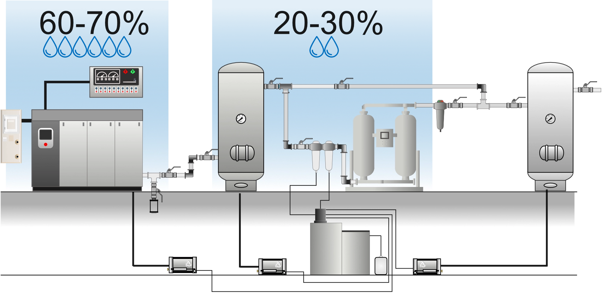
- Aftercooler: main condensation area — where we want to capture it
- Receiver: secondary condensation + liquid settling
- Piping (low points): accumulation if there is no slope, collection points or drain
- Point of use: last critical place — often “too late”
Role of each piece of equipment
- Aftercooler: forces condensation early, in a controllable area
- Water separator: removes bulk liquid — never 100 % effective
- Coalescing filter: captures aerosols/mist — not vapor
- Drains: discharge the collected condensate — often more critical than the rest
- Dryer: the only equipment that removes vapor (lowers the PDP)
Common causes of water problems
- Insufficient cooling (aftercooler) or a fouled / undersized water separator
- Drains blocked, undersized, poorly set or bypassed
- Network with no slope, no collection points, or with poor drainage points
- Believing that a filter “dries” the air (a filter mainly handles liquid and aerosols, not vapor)
Best practices — field actions
- Remove water as early as possible: aftercooler → water separator → automatic drain
- Regularly check and test all drains and collection points
- Install drip legs at low points + a dedicated drain
- Take air outlets from the top of the main line
Thermodynamic principles
Compression strongly raises the air temperature. Downstream, the air cools (aftercooler, receiver, piping). When the temperature drops below the pressure dew point (PDP), the water vapor condenses into liquid. The strategy is to force this condensation in controlled areas, then discharge the condensate efficiently.
Water separator efficiency
A water separator removes droplets (free water / bulk liquid), but does not lower the dew point. Any remaining vapor stays in the air and may condense farther on if the network passes through a colder zone.
Drain sizing
- Estimate the expected condensate flow (L/h) based on the flow in CFM and the inlet conditions.
- Select automatic drains (electronic, float or “zero-loss”) able to discharge that flow.
- Allow a 20–30 % margin for load peaks, seasonal humidity and over-flow periods.
Dryer selection
- Refrigerated: typical PDP ≈ 3 °C (38 °F) — common industrial applications.
- Desiccant: PDP −40 °C (−40 °F) or lower — instrumentation, critical processes.
- Validate the ISO 8573-1 class required by the process (customer / quality specification).
Dew point problems — causes and diagnosis
The pressure dew point (PDP) is the temperature at which water vapor begins to condense in compressed air, at the operating pressure (e.g. 100 PSIG). A PDP that is too high immediately increases the risk of downstream condensation, especially where there are colder network sections.
Factors affecting dryer performance
| Factor | Impact on the PDP | Recommendation |
|---|---|---|
| Inlet air temperature | +20 °F of compressed air → 35 to 50 % drop in dryer performance | Keep the inlet T° ≤ 100 °F (38 °C) at the filters and dryer |
| Ambient temperature | +10 °F → PDP rises by ~3–5 °F depending on the dryer | Compressor room ≤ 100 °F, adequate ventilation |
| Flow above capacity | Overload → PDP rises quickly | Never exceed 100 % of the rated capacity |
| Inlet pressure | Low pressure → reduced efficiency | Respect the specified minimum pressure (usually ≥ 80 PSIG) |
| Heat exchanger fouling | Reduced heat transfer → high PDP | Periodic cleaning of the fins / condenser |
| Refrigerant charge | Leak = loss of capacity | Check annually, repair leaks |
Practical rules
- The 20 °F rule: for every 20 °F (11 °C) above 100 °F at the inlet, the refrigerated dryer’s capacity drops by about 40 %.
- Safety margin: size the dryer at the maximum flow, taking the aftercooler’s CTD into account.
- Atmospheric vs pressure dew point: a PDP of 38 °F (3 °C) at 100 PSIG is equivalent to an atmospheric dew point of about −22 °C (−8 °F).
- Downstream condensation: if the piping passes through a zone colder than the PDP, water will condense — even with a working dryer.
Diagnosing a high PDP — checklist
- Check the inlet air temperature (≤ 100 °F?)
- Check the actual flow vs the dryer rated capacity
- Inspect the condenser / heat exchanger (fouling, fan)
- Check the refrigerant charge (sight glass, HP/LP pressures)
- Check that the dryer drain is working
- Measure the PDP with a calibrated hygrometer (not just the built-in display)
- Check the upstream coalescing filter (ΔP, saturation)
ISO 8573-1 classes — dew point
| Class | Max. PDP (°C) | Max. PDP (°F) | Typical application |
|---|---|---|---|
| 1 | −70 | −94 | Electronics, semiconductors |
| 2 | −40 | −40 | Instrumentation, critical processes |
| 3 | −20 | −4 | Painting, sensitive applications |
| 4 | +3 | +37 | General industry (refrigerated dryer) |
| 5 | +7 | +45 | Low-demand applications |
| 6 | +10 | +50 | Basic use, pneumatic tools |
Source: ISO 8573-1:2010. The PDP is measured at the operating pressure, not at atmospheric pressure.
Standards and references
- ISO 8573-1:2010 — Compressed air purity classes
- ISO 7183 — Dryer specifications and testing
- CAGI Data Sheets — Compressor and dryer performance